
Email us
coco20.xu@gmail.comContact Number
/
If you're designing battery packs for an EV platform or specifying interconnects for a utility-scale BESS rack, you've probably noticed that the connectors are where most field failures happen. A cable either works or it doesn't — but a connector can start off fine and degrade over time in ways that are hard to catch until something fails.
The reason is simple: connectors are the interface between different materials, different thermal expansion rates, and different assembly processes. Get the design right and they'll outlast the battery. Get it wrong and you're looking at voltage drop, insulation breakdown, or in the worst case, a thermal event.
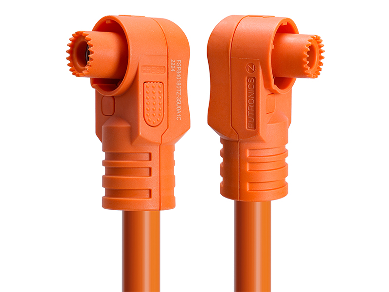
This guide covers the engineering essentials for high-voltage connectors in EV and BESS applications — the parameters that actually matter when you're selecting or specifying a connector for 400V to 1500V systems.
The first thing to understand is that "rated for 1000V" on a datasheet doesn't mean much if your application doesn't account for the real-world conditions around the connector.
Two terms that come up constantly in HV connector design:
For a 800V DC bus in an EV battery pack, IEC 60664-1 usually calls for clearance distances around 8mm to 12mm depending on pollution degree and altitude derating. Creepage distances need to be larger — typically 12mm to 16mm — because contamination on the surface (dust, moisture, salt) can create a conductive path that wouldn't exist in clean air.
A mistake we've seen more than once: A designer specs a connector that passes hi-pot testing in the lab, but after 18 months in the field, the creepage path accumulates enough contamination to trigger tracking failure. The fix is always the same — specify creepage distances based on the pollution degree of your actual operating environment, not the lab conditions.
This is a topic that's become much more important as battery voltages climb past 800V. Partial discharge is a localized electrical breakdown that doesn't fully bridge the electrodes — it's like a tiny spark inside a void in the insulation. Over thousands of cycles, it erodes the material from the inside out until something fails catastrophically.
For connectors used in 800V+ systems, make sure the supplier provides PD test data at 1.5× the operating voltage. If they can't or won't, that's a red flag.
High-Voltage Interlock Loop (HVIL) is something every engineer working on EV battery systems should know inside out. It's a low-voltage circuit that runs alongside the high-voltage path, physically wired so that if you unseat any connector in the chain, the HVIL breaks before the main power contacts disconnect.
When the HVIL circuit opens, the battery management system (BMS) knows a connector has been disturbed and can discharge the DC bus capacitors or open the contactors before anyone touches a live terminal.
The key insight: HVIL isn't optional. If you're designing a battery pack or BESS rack that operates above 60V DC and stores enough energy to be hazardous, a properly integrated HVIL circuit is what makes the system safe for technicians to service.
For the main power path in an EV or BESS system, you're typically looking at continuous currents from 100A to over 500A. The contact interface is where the heat is generated.
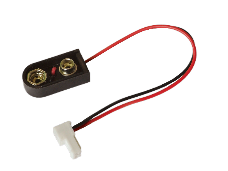
For conductors from 2 AWG up to 4/0 AWG (35mm² to 120mm²), crimping isn't like small-signal connector assembly. A few things that matter:
For heavy-duty BESS battery rack interconnects, a High-Flex BESS Battery Rack Power Cables solution with properly engineered crimp terminations ensures reliable power transmission over the system's lifetime.
For high-current battery connectors, the plating on the contact interface determines long-term stability:
For EV battery packs, a common hybrid approach is silver-plated power contacts for the main current path with gold-plated signal contacts in the same connector housing.
An EV battery pack connector that sits under the vehicle needs to handle:
- Pressure washing (directed water jets at 100 bar)
- Salt spray (road salt in winter climates)
- Condensation from thermal cycling
- Dust ingress (especially for BESS installations in desert environments)
IP67 is the baseline for external battery connectors. But IP67 alone doesn't guarantee long-term sealing — the seal design, material selection, and assembly process all matter.
A well-designed connector will have separate sealing points for the wire entry (wire seal or grommet), the mating interface (housing seal), and the mounting surface (gasket or O-ring).
For applications requiring reliable thermal performance at elevated temperatures, a High-Temperature Battery Power Connector AWG 12 provides the thermal stability needed for battery-side connections.
At 300A continuous, a contact resistance of just 0.1 mΩ generates 9 Watts of heat — per contact pair. Multiply that by the number of connections in a pack and you've got a significant thermal load to manage.
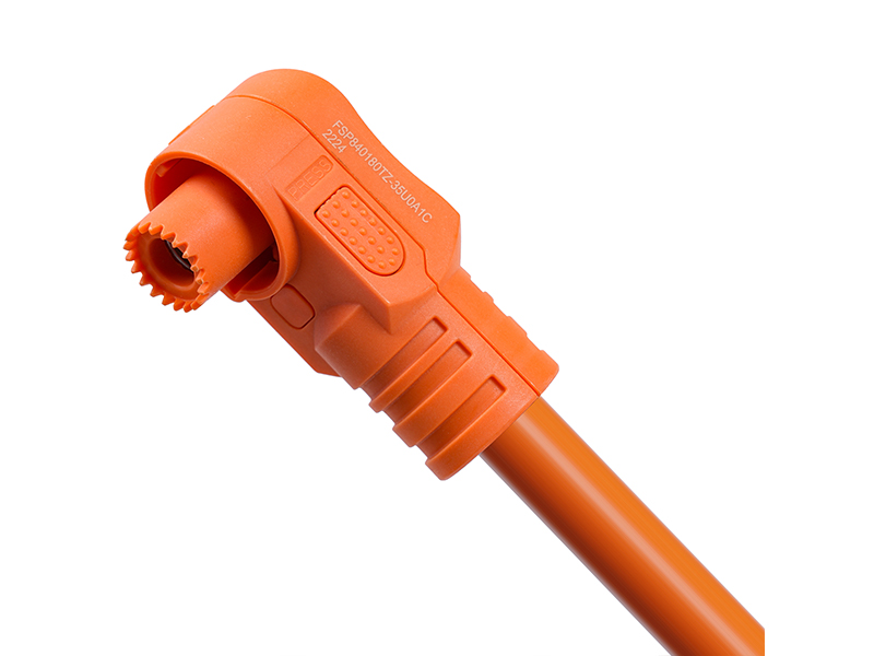
UL 1977 specifies a maximum temperature rise of 30°C above ambient at rated current for power connectors. But for sealed battery pack connectors operating at high ambient temperatures (60°C+), a 30°C rise means the contact interface hits 90°C — right at the edge of what standard insulation materials can handle long-term.
What we've found works: Derate the connector's current rating by 15-20% for sealed, high-ambient applications. And always run thermal validation on the actual assembled pack, not just the connector in isolation — the heat from neighboring cells and busbars changes the thermal picture significantly.
For complete high-voltage battery systems, a High-Voltage Lithium Battery Wire Harness designed with proper thermal margins will outperform a generic assembly in long-term reliability.
| Parameter | Low-Voltage (12-60V) | High-Voltage (400-800V) | Ultra-High (1000-1500V) |
|---|---|---|---|
| Creepage | ≥3mm | ≥12mm | ≥20mm |
| Clearance | ≥1.5mm | ≥8mm | ≥14mm |
| Partial Discharge | Not required | Recommended | Mandatory |
| HVIL | Optional | Required | Required |
| Seal Rating | IP40-IP54 | IP67 | IP67-IP69K |
| Typical Standard | UL 1977 | UL 1977 + IEC 62893 | IEC 62893 + UL 4128 |
High-voltage connectors are one of the most critical — and most overlooked — components in EV and BESS systems. Getting the design right means paying attention to creepage and clearance for the voltage level you're actually running, integrating HVIL as a non-negotiable safety feature, verifying crimp quality on every single contact, and testing the seal and thermal performance in the conditions your system will actually see.
Whether you're specifying UL 1977 rated power connectors for a new battery module or designing a custom HVIL harness for a BESS rack, the engineering details that go into the connector interface are what separate a reliable system from one that comes back under warranty.
If you are interested in our products and want to know more details, please contact us, and we will reply to you as soon as we can.



 IPv6 network supported